The DDS module used to generate the RF signal for the Raspberry Pi Wobbulator is based on the AD9850 frequency synthesizer chip
and is available from a number of suppliers on eBay. There are a few variations
on the design of the module but the one used in this project is shown in below (mounted on a breadboard for initial testing).

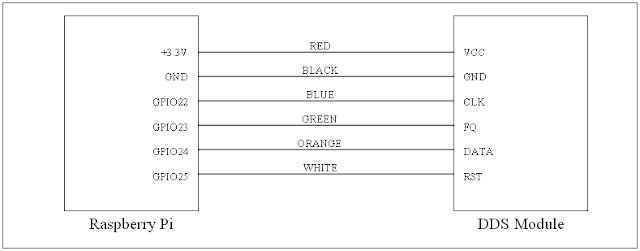
The DDS module was connected directly to the GPIO header on the Raspberry Pi using “flying leads” according to the following schematic. Note that the VCC pin on the DDS module is connected directly to the 3.3V pin on the Raspberry Pi to ensure compatibility with the 3.3V TTL logic levels used by the Raspberry Pi.
The DDS module must be loaded with a 40 bit control word and this is achieved by programming the GPIO pins on the Raspberry Pi to communicate with the DDS module. A quick online search resulted in a simple Python program for controlling the DDS module being found on M0XPD’s “Shack Nasties” blog.
This code was rewritten to work with Python 3 (and also to use different GPIO pins) and a simple GUI designed and programmed to allow the user to choose the frequency and to start and stop the DDS module - effectively creating a simple and cheap RF signal generator, which I (rather unimaginatively) called the "RPi RF Signal Generator" (or "RPi RFSigGen" for short). A screenshot of the user interface of the RPi RFSigGen is shown below.

You can download the RPi RFSigGen Python 3 source code from GitHub as a "zip" archive. Extract all the files, launch IDLE3 (the Python 3 Integrated Development Environment bundled with the Raspbian "Wheezy" operating system), and open the file "rpi_rfsiggen.py". You should see the source code appear in a separate window. Select "Run -> Run Module" from the menu, or simply press "F5" to run the program, but note that the program must be run with "root" privileges or as “sudo”.
The most convenient way to do this is to open the "idle3.desktop" file in Leafpad and edit it by inserting "sudo " in front of "/usr/bin/idle3" as shown below (I've highlighted the required change to make it stand out). Now every time you launch IDLE3 by double clicking on the IDLE3 icon on your LXDE desktop, you will have root privileges.

Alternatively, you can launch IDLE3 with root privileges by typing the following at the command line prompt in a terminal window and pressing Enter (but you have to do this every time you want to launch IDLE3 as sudo).
pi@raspberrypi ~ $ sudo idle3_
So, I used the RPi RFSigGen program to test the DDS module at various frequencies across the HF spectrum.There are two sine wave outputs available on the DDS module (“sin A” and “sin B”) and the waveform and spectrum of the outputs from both were examined at various frequencies up to around 30MHz. The output from “sin B” was found to be much cleaner than the output from “sin A” and largely free from harmonic distortion. The output from "sin B" in the frequency domain is shown below for 21 MHz. You can see that the output at third and fifth harmonics is very low, and this was typical of the performance of the DDS module right across the HF spectrum. Please ignore the large peak at the lower end of the spectrum (around 4MHz) – this is an spurious signal that is always present (even when there's no RF input!).

The DDS module must be loaded with a 40 bit control word and this is achieved by programming the GPIO pins on the Raspberry Pi to communicate with the DDS module. A quick online search resulted in a simple Python program for controlling the DDS module being found on M0XPD’s “Shack Nasties” blog.
This code was rewritten to work with Python 3 (and also to use different GPIO pins) and a simple GUI designed and programmed to allow the user to choose the frequency and to start and stop the DDS module - effectively creating a simple and cheap RF signal generator, which I (rather unimaginatively) called the "RPi RF Signal Generator" (or "RPi RFSigGen" for short). A screenshot of the user interface of the RPi RFSigGen is shown below.
You can download the RPi RFSigGen Python 3 source code from GitHub as a "zip" archive. Extract all the files, launch IDLE3 (the Python 3 Integrated Development Environment bundled with the Raspbian "Wheezy" operating system), and open the file "rpi_rfsiggen.py". You should see the source code appear in a separate window. Select "Run -> Run Module" from the menu, or simply press "F5" to run the program, but note that the program must be run with "root" privileges or as “sudo”.
The most convenient way to do this is to open the "idle3.desktop" file in Leafpad and edit it by inserting "sudo " in front of "/usr/bin/idle3" as shown below (I've highlighted the required change to make it stand out). Now every time you launch IDLE3 by double clicking on the IDLE3 icon on your LXDE desktop, you will have root privileges.
Alternatively, you can launch IDLE3 with root privileges by typing the following at the command line prompt in a terminal window and pressing Enter (but you have to do this every time you want to launch IDLE3 as sudo).
pi@raspberrypi ~ $ sudo idle3_
So, I used the RPi RFSigGen program to test the DDS module at various frequencies across the HF spectrum.There are two sine wave outputs available on the DDS module (“sin A” and “sin B”) and the waveform and spectrum of the outputs from both were examined at various frequencies up to around 30MHz. The output from “sin B” was found to be much cleaner than the output from “sin A” and largely free from harmonic distortion. The output from "sin B" in the frequency domain is shown below for 21 MHz. You can see that the output at third and fifth harmonics is very low, and this was typical of the performance of the DDS module right across the HF spectrum. Please ignore the large peak at the lower end of the spectrum (around 4MHz) – this is an spurious signal that is always present (even when there's no RF input!).

The accuracy of the frequency output from the DDS module was also
checked using a frequency counter and was found to be within a few Hertz of the
specified frequency and also showed little or no drifting over time. The level of output from the "sin B" output on the DDS module was found was found to be fairly
constant (between 0.3V peak and 0.4V peak) over the HF spectrum, although the output was found to have a DC component. Therefore I decided to use DC blocking capacitors on the DDS output.
I decided to mount the DDS module on an Adafruit prototyping board. PCB pins were soldered to the prototyping board for the various outputs from the DDS module, and an SMA socket was mounted on the prototyping board to provide a coax output. DC blocking capacitors (1000pF or 1nF) were soldered on the "sin B" output from the DDS module to remove any DC component, but these are not visible on the photo below because they are on the underside of the prototyping board.

As before, GPIO pins 22, 23, 24, and 25 are used to control the DDS module, but the wiring is now very straight forward due to the convenient location of the the "break-out" terminals for these pins on the prototyping board.
My next post will look at how to use an ADC module with the Raspberry Pi to measure analogue voltages.
My next post will look at how to use an ADC module with the Raspberry Pi to measure analogue voltages.
thanks a lot for your knowledge :)
ReplyDeleteTimi
Can you send a picture of the underside?
ReplyDeleteRobbert
What is the freq range of this project? I wonder if you please consider on these posts adding an approximate price for these various projects so that we could get some idea ?
ReplyDeleteAD9850 = 0 to 40MHz...
ReplyDeleteNow to find someone who has written an AD9850 parallel mode FM driver for the Pi.
How would the code have to be changed to create a phase shift of the Sin B output relative to the Sin A output. Additionally, is it possible to create a DC offset of 0.5V to make the sine wave outputs centered at 0.5V instead of 0V? THanks
ReplyDeleteHi!
ReplyDelete