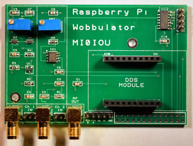
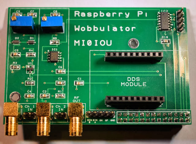
Now its time to start soldering the remaining through hole components, which are mostly connectors of one sort or another. You'll need to change the tip on your soldering iron to a thicker one, or use a soldering iron with a thicker tip.
Start by soldering the three PCB mount right-angles SMA sockets J1 to J3. Each of these sockets have five terminals, four of which are ground connections and are connected directly to the metal casing of the socket, which acts as a heatsink. For this reason these sockets are quite difficult to solder - they require a lot of heat and I found that increasing the temperature of my soldering iron helped considerably. Next insert the two multiturn potentiometers VR1 and VR2 and solder them in place, remembering to trim the terminals back flush with the soldered joint.
Next attach PCB pin terminals PL2, PL4, PL5 and PL 6 (which are 5-way, 4-way, 2-way and 2-way terminals respectively) and solder in place. Then insert the two 10-way PCB sockets PL3A and PL3B and solder in place. The DDS module will be plugged into these sockets, but you can solder the DDS module directly on to the Raspberry Pi Wobbulator PCB if you prefer, in which case you won't need the sockets.
Finally, insert the 26-way GPIO header from the underside of the PCB and solder in place. The completed Raspberry Pi Wobbulator is shown below.
And the following photo shows what the underside of the PCB should look like. The two large holes on the Wobbulator PCB line up with the holes in the later versions of the Raspberry Pi PCB and can be used to securely connect the Wobbulator PCB to the Raspberry Pi PCB using PCB spacers if you prefer
All that remains to do is to plug your DDS module into the Wobbulator PCB and then connect the Wobbulator PCB to your Raspberry Pi by plugging it into the GPIO header. The following photo shows the final assembly, ready for testing.
My next blog post will give details of the setup and testing procedures for the Raspberry Pi Wobbulator. If you are interested in getting your hands on a Raspberry Pi Wobbulator PCB or component kit then please visit www.cutpricecables.co.uk/irpiwobbulator.html . The PCB is priced at £12.00, and the PCB plus kit of components is priced at £40. This includes all sales taxes and free worldwide delivery. You can purchase online and pay by credit or debit card, or PayPal.
Monday 30 December 2013
Sunday 29 December 2013
Building the Raspberry Pi Wobbulator Kit - Part 1
I took delivery of the the Raspberry Pi Wobbulator PCBs a few days ago and I've put a kit of components together to go with the PCB. The PCB is priced at £12.00, and the PCB plus kit of components is priced at £40. This includes all sales taxes and free worldwide delivery. The PCBs and kits are available here if you are interested. You can purchase online and pay by credit or debit card, or PayPal.
The Raspberry Pi Wobbulator PCB is shown above. Assembly is fairly straight forward, but in this blog post and the next I'll go the assembly step-by-step and highlight any potential problems. This blog post deals with the surface mount components. I assume you have had some experience of soldering surface mount components, but in any case you will need a fine tipped temperature controlled soldering iron, some small diameter solder (0.5mm or smaller), a pair of tweezers and some kind of magnifier. I use a head mounted magnifier which leaves both hands free, but a good illuminated magnifier lamp would also be suitable.
Start off by soldering on the five 1 nF capacitors, C1 to C5 in place. Their positions are clearly marked on the PCB and it doesn't matter what was round they are soldered. These surface mount capacitors do not have their value marked on them, so it is important not to get them mixed up with other value capacitors! So please only work with one value of capacitors at any given time. The following photo shows the PCB with capacitors C1 to C5 soldered in place.
Next, solder the five 100 nF capacitors, C6 to C10 in place. Your PCB should now look the same as shown in the following photo.
Next, solder the five resistors R1 to R5 in place. Unlike the capacitors, the resistors do have their value marked on them in the form of a three digit number. The first two digits represent the value, and the third digit is the multiplier. So, for example, the 56 Ohm resistor R1 is marked "560", which means "56 followed by 0 zeros", in other words, "56". R2 is marked "105" which means "10 followed by 5 zeros", in other words 1000000 Ohms, or 1 M Ohm. Similarly R3 is marked "222", R4 is marked "470" and R5 is marked "103". The following photo shows the PCB with all five resistors in place
Next it's the turn of the discrete semiconductors. There is one transistor U1, and two diodes D1 and D2. The direction in which the diodes are soldered in place is important - they are marked (all be it very faintly) with a line at one end, and this corresponds to the line on the diode symbol. A closeup view of D1 is shown below - you can just about make out the line on the left-hand end of the component.
The following photo shows the PCB with the discrete semiconductors in place.
Finally, it's time to solder the ICs in place. Both ICs are Narrow Body Standard Small Outline Package format, or SOIC_N for short. I soldered them in place by first melting a small amount of solder on each pad on the PCB and then placing the IC in position and carefully pressing each "leg" down with the tip of the soldering iron until the solder melted and attached to the leg. Use whatever method works for you! The following photo shows the PCB with the IC's in position.
Congratulations! That's all the surface mount components in place - time to lie down in a darkened room until your eyesight recovers and your hands stop shaking... hi hi!
My next blog post will deal with soldering the remaining (through hole) components in place.
Monday 9 December 2013
Raspberry PI Wobbulator PCB
The Raspberry Pi Wobbulator PCB is shown below. The PCB is double sided and is designed to be mounted directly above the Raspberry Pi motherboard. It was designed using DesignSpark PCB (which is available free from RS Components) and an initial batch of PCBs is currently being manufactured. I hope to take delivery of them some time around Christmas or the New Year.
I hope to make the PCB available on its own, or along with a kit of components for home assembly. I'm currently working on sourcing the various components at the best price possible. The bare PCB on its own will be £12 (£10 + VAT) and this price will include free delivery within the UK. Worldwide delivery is available at a small additional cost depending on your location. I'm still working on putting together the best deal I can for the kit of components.
For the latest information on possible delivery date and pricing I would suggest that you join the rpiwobbulator Yahoo Group. I will be posting up to date information on delivery and pricing as it becomes available on the Yahoo Group rather than on this blog, but you can of course contact me directly if you wish via email.
Subscribe to:
Posts (Atom)


